Description
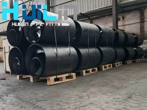
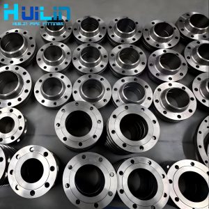
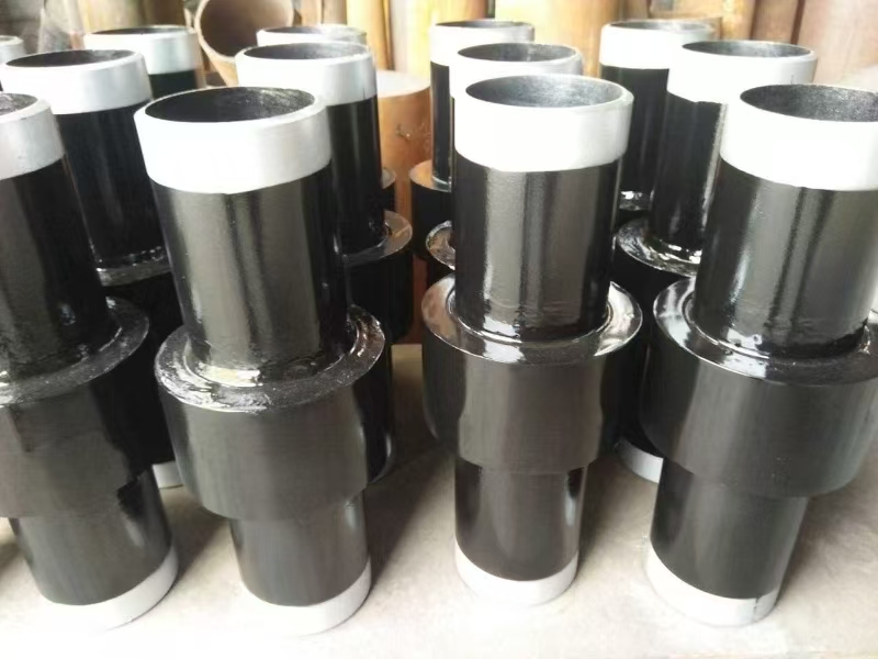
Large diameter insulated flange, carbon steel, stainless steel, high-voltage insulated flange, specialized insulated joint for petroleum and natural gas pipelines
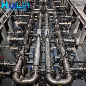
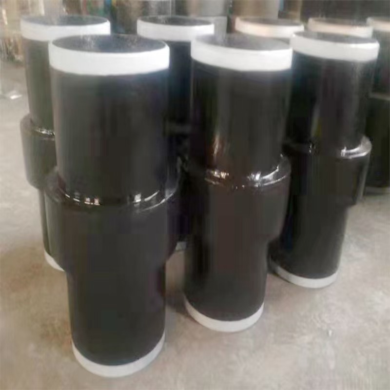
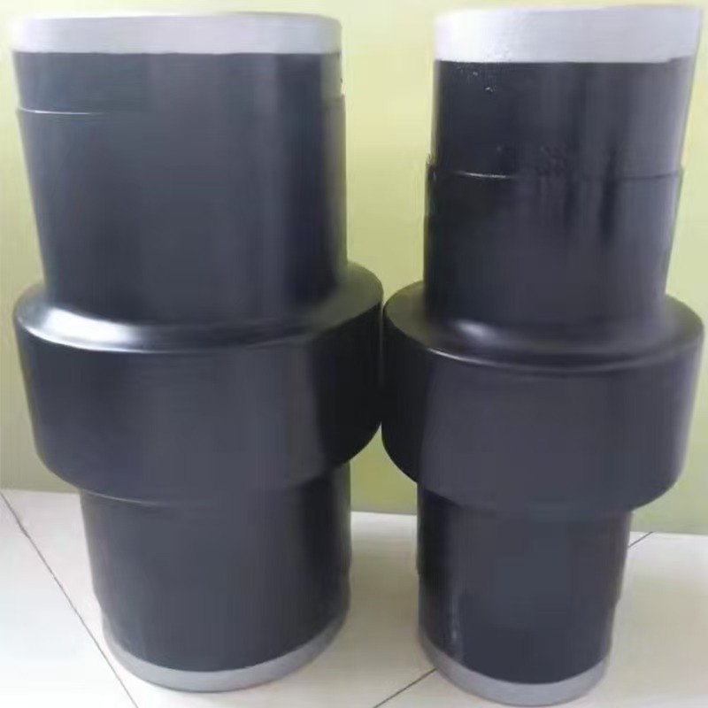
Insulated joints are key pressure components of cathodic protection systems for buried steel pipelines, mainly used to isolate pipeline electrochemical corrosion and suitable for pipelines transporting media such as oil, gas, water, and chemical raw materials. It is composed of components such as composite parts, insulation boards, fillers, sealing rings, etc. It adopts an integral structure (upper/lower pipes, sleeves, insulation parts and seals) and a double sealing design (DSGS patented technology), which combines sealing performance and pressure bearing capacity.
The core parameters of this product include 2500V insulation strength, ≥ 6M Ω insulation resistance, and have passed a water pressure test at 1.5 times the design pressure, meeting the SY/T0516 industry standard. It adopts a combination of rigid insulation rings and U-shaped sealing rings internally to form a sealed container structure, which can withstand soil pressure and pipeline operation loads, and has a service life synchronized with the pipeline. The main types include rail type and pipeline specific type. The former uses groove type insulation board combined with high-strength bolts, while the latter strengthens insulation and pressure performance through sleeve welding technology.
During installation, avoid welding operations near the joints and cooperate with the overall pressure test of the pipeline. As an improved product of insulation flanges, it solves the problems of traditional flange leakage and insufficient stiffness, and has become a standardized component of cathodic protection systems.
Parameters
Pressure rating: PN1.0~PN40MPa
Insulation strength: 2500V (50Hz, no breakdown for 1 minute)
Insulation resistance: ≥ 6M Ω (DC 1000V)
Hydraulic test: 1.5 times the design pressure
Applicable temperature: -45 ℃ to 100 ℃
Size range: DN15 to DN1200
Rubber bonded insulation joints for tracks
Shear strength: ≥ 2700kN (50kg/m type)
Electrical performance: Dry state insulation resistance>20M Ω
Working temperature: -60 ℃ to+80 ℃
Waterproof rating: IP68
Size: Clamp length 424mm ± 0.5mm
Gas insulated joint
Insulation resistance: ≥ 500M Ω
Electrical strength: 5000V
Structure: Polyvinyl chloride (PVC)+Fluoroplastic material
Installation feature: Avoid long-term contact between gas and plastic parts, extend service life
Different standards correspond to different application scenarios, which need to be selected according to specific working conditions
Sizes
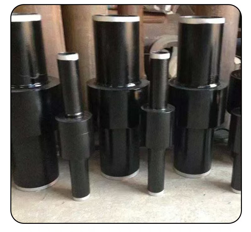
Common caliber range
DN100: Suitable for connecting small-diameter pipelines
DN350: Common diameter of SY/T0516 national standard mining insulation joint, made of high temperature resistant carbon steel material
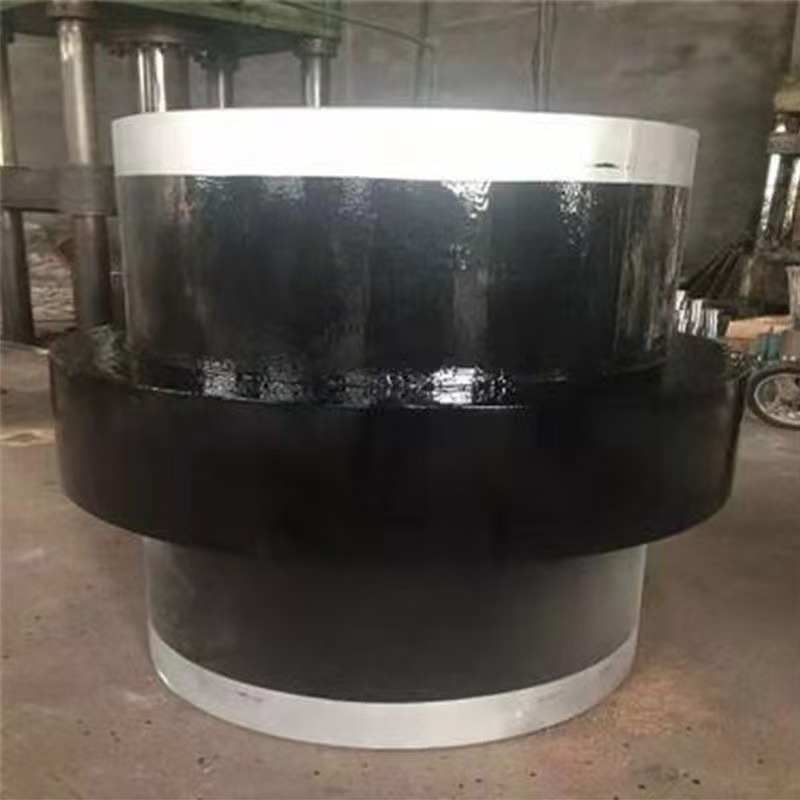
DN400: Representative specification for large-diameter insulated joints, made of carbon steel material
DN650: Large diameter insulated joint suitable for petrochemical pipelines
Standard
NB/T 47054-2016: Suitable for pipeline conditions with nominal diameter ≤ 600mm and design pressure ≤ 16MPa, or nominal diameter ≤ 1400mm and design pressure ≤ 12MPa, with a temperature range of -45 ℃ to 100 ℃.
SY/T 0516-2008: Suitable for buried steel pipeline systems with design pressure ≤ 10MPa and temperature range of -20 ℃ to 250 ℃
Testing
The testing of insulation joints mainly includes methods such as potential method, current method, and volume resistivity detection, and appropriate testing methods need to be selected according to specific scenarios.
Potentiometric testing
The insulation performance is judged by measuring the potential difference between the protective side and the non protective side of the tube. The normal potential difference is 200~500mV. During testing, the cathodic protection power supply in the station needs to be turned off to avoid interference from the anode voltage field with the reference electrode potential. If the potential difference is less than 100mV, further confirmation of the insulation state is required.
Current method testing
Including PCM current method and current loop method:
PCM current method: Apply signal current to the pipeline outside the station and measure the current in the pipeline inside the station. Under normal circumstances, the current accounts for 10% to 20% of the transmitter current. If there are abnormally high currents or potential fluctuations, there may be poor bonding or insulation.
Current loop method: By increasing the output current of the cathodic protection power supply, measure the current in the pipeline at the ground level. If there is an insulated joint, there should be no current or only a trace current at that location.
Volume resistivity detection
The megohmmeter method is used to test the resistance value of insulation materials, which requires disconnecting the power supply and fully discharging before proceeding. The insulation resistance value of new equipment should be ≥ 100M Ω, and the resistance value of equipment with longer service life should be ≥ 1M Ω
precautions
The test should be conducted in a dry and dust-free environment to avoid poor wire contact.
If the ambient temperature is below 5 ℃, it is necessary to adjust the testing conditions or extend the drying time