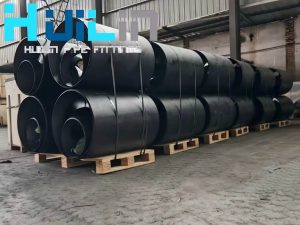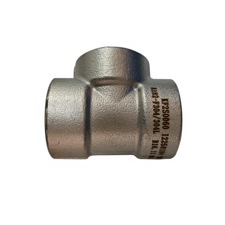
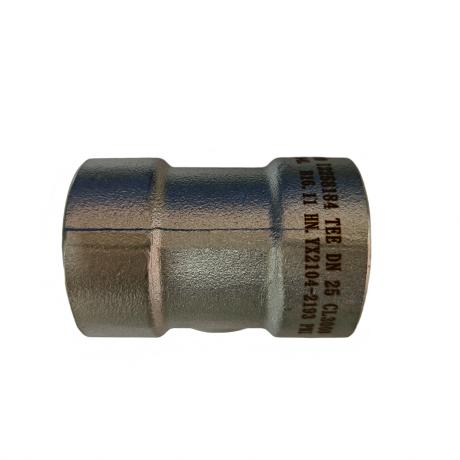
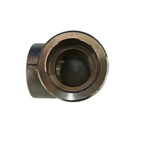
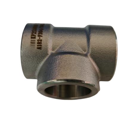
A tee is a type of chemical pipe fitting mainly used to change the direction of fluid flow, usually used at the branching point of the main pipeline. A tee has three openings, namely one inlet and two outlets, or two inlets and one outlet, with T-shaped and Y-shaped shapes, divided into equal diameter tees and reducing tees
Equal diameter tee: The size of the connecting end is the same.
Reducing tee: The size of the main pipe connection is the same, but the size of the branch pipe connection is smaller than that of the main pipe
manufacturing process
The manufacturing process of tees includes hydraulic bulging, etc. Liquid is injected into the pipe blank through a dedicated hydraulic press, and the pipe blank is extruded through the movement of the hydraulic press to form a branch pipe
Specification:
- Sizes: Seamless Size:DN15-DN1200
Welded Size:DN200-DN2000
- Thickness:SCH10;SCH20;SCH30;STD;SCH40;SCH60;SCH80;SCH100;SCH120;SCH160;XS;XXS; Max 150mm
- Materials:
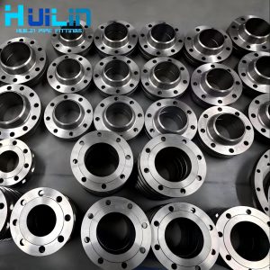
Carbon steel flange (CS) : ASTM A105, ASTM A350 LF1, LF2 CL1/CL2, LF3 CL1/CL2, ASTM A694 F42, F46, F48, F50, F52, F56, F60, F65, F70;
Stainless steel flange (SS) : ASTM A182 F304, 304L, F316, 316L, 1Cr18Ni9Ti, 0Cr18Ni9Ti, 321, 18-8;
Alloy flange (AS) : ASTM A182F1, F5a, F9, F11, F12, F22, F91, A182F12, A182F11, 16MnR, Cr5Mo, 12Cr1MoV, 15CrMo, 12Cr2Mo1, A335P22, ST45.8;
- Standards:
ASME B16.9; GB12459; DIN2616; GOST17378-2001; JIS B2311
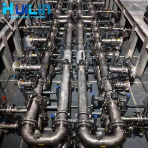
- Application:
Water treatment; Power plant accessories; Chemical engineering; Shipbuilding; Nuclear energy; Garbage disposal; natural gas; petroleum
| Nominal Size | Depth of Socket | DimensindSodket | Wall Thickness Cmin | Center to Bottom of Socket 45°Lateral | ||||||||
| A | H | |||||||||||
| DN | NPS | Jmin | d1 | 3000LB | 6000LB | 9000LB | 3000Y F | 6000LB | 3000LB | 6000LB | ||
| Sch80 | Sch160 | XXS | Sch80 | Sch160 | Sch80 | Sch160 | ||||||
| 6 | 1/8 | 10 | 10.7 | 3.2 | 3.5 | 二 | 二 | |||||
| 8 | 1/4 | 10 | 14.1 | 3.3 | 4 | 32 | 8 | |||||
| 10 | 3/8 | 10 | 17.5 | 3.5 | 4.4 | 37 | 8 | 一 | ||||
| 15 | 1/2 | 10 | 21.8 | 4.1 | 5.2 | 8.2 | 41 | 51 | 11 | 13 | ||
| 20 | 3/4 | 13 | 27.4 | 4.3 | 6.1 | 8.6 | 51 | 60 | 13 | 14 | ||
| 25 | 1 | 13 | 34.2 | 5 | 7 | 10 | 60 | 71 | 14 | 18 | ||
| 32 | 1.1/4 | 13 | 42.9 | 5.3 | 7 | 10.6 | 71 | 81 | 18 | 21 | ||
| 40 | 1.1/2 | 13 | 48.3 | 5.6 | 7.8 | 11.2 | 81 | 98 | 21 | 25 | ||
| 50 | 2 | 13 | 61.1 | 6.1 | 9.5 | 12.2 | 98 | 120 | 25 | 29 | ||
| 65 | 2.1/2 | 16 | 76.9(73.8) | 7.7 | 12.5 | 二 | ||||||
| 80 | 3 | 16 | 89.8 | 8.3 | 13.8 | 二 | ||||||
| 100 | 4 | 19 | 115.5 | 9.4 | – | |||||||
| Note: | ||||||||||||
| Average of socket wall hickness around periphery shallbe no les thanlisted values.The minimum values are permitted in localized areas |
||||||||||||