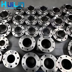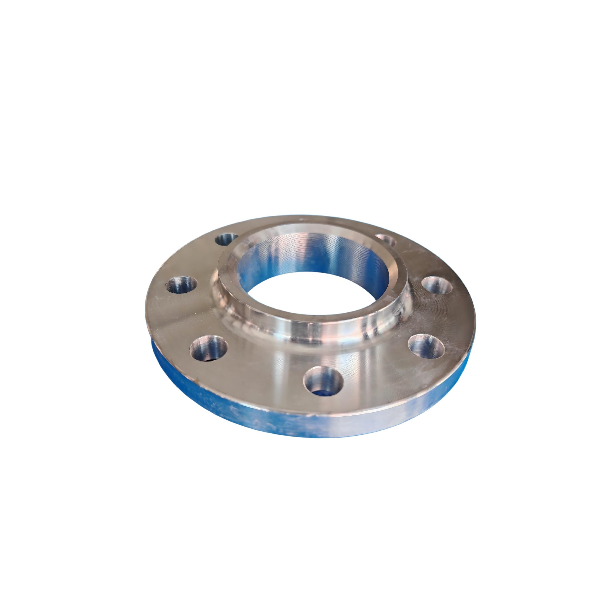
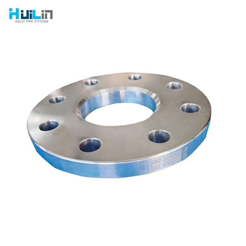
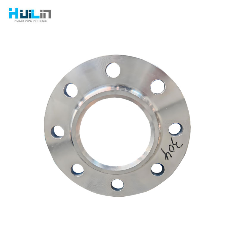
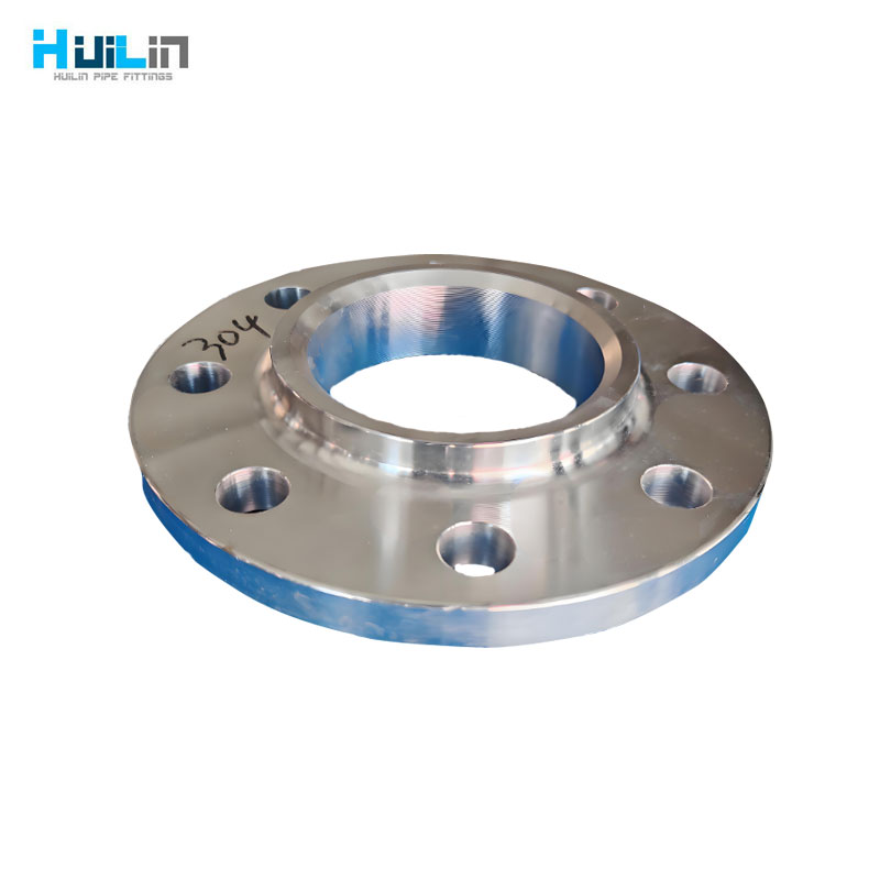
Slip on flange refers to a type of flange that is connected to a container or pipeline using fillet welds. It belongs to any type of flange. When designing, check the integrity of the connection between the flange ring and the straight cylinder section according to the integral or loose flange. There are two types of flange rings: those with necks and those without necks. Compared with neck welding flanges, slip on flanges have a simpler structure and lower material consumption, but their stiffness and sealing performance are not as good as neck welding flanges. Slip on flanges are widely used for connecting medium and low pressure vessels and pipelines.
Slip on flanges are suitable for pipeline systems with relatively low pressure levels, where pressure fluctuations, vibrations, and oscillations are not severe. The advantage of flat welding flanges is that they are easier to align during welding assembly and are relatively inexpensive, thus they have been widely used.
Specification:
- Sizes:1/2”-120”;DN15-DN3000
- Materials:
Carbon steel flange (CS) : ASTM A105, ASTM A350 LF1, LF2 CL1/CL2, LF3 CL1/CL2, ASTM A694 F42, F46, F48, F50, F52, F56, F60, F65, F70;
Stainless steel flange (SS) : ASTM A182 F304, 304L, F316, 316L, 1Cr18Ni9Ti, 0Cr18Ni9Ti, 321, 18-8;
Alloy flange (AS) : ASTM A182F1, F5a, F9, F11, F12, F22, F91, A182F12, A182F11, 16MnR, Cr5Mo, 12Cr1MoV, 15CrMo, 12Cr2Mo1, A335P22, ST45.8;
- Standards:
ASME B16.5; HG20592; DIN2527、2573、2627-2638、2673、2552、2653、2655、2656、2641、2642、2565-2569; GOST12820; JIS B2220
- Application:
Water treatment; Power plant accessories; Chemical engineering; Shipbuilding; Nuclear energy; Garbage disposal; natural gas; petroleum
| 16BAR | ||||||||||||||||||
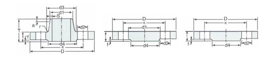
| Bore | Common Dimention | Welding Neck | Raised Face | Driling | Approx Weght(kg) | |||||||||||||
| Norminal Bore |
d1 | D | WekingNeck | t | K | T | d3 | s | a | d4 | f | Number of Bolt | Daof Bot | d2 | DIN 5276 | DIN 2632 | ||
| Slop-on | Bild | |||||||||||||||||
| 10A | 14) 17.2* | 90 | 14 | 14 | 60 | 35 | 25 | 1.8 | 4 | 6 | 40 | 2 | 4 | M12(12) | 14 | 0.63 | 0.58 | |
| 28 | ||||||||||||||||||
| 15A | 20) 21.3* | 95 | 14 | 14 | 14 | 65 | 35 | 30 | 2 | 4 | 6 | 45 | 2 | 4 | M12(12”) | 14 | 0.72 | 0.648 |
| 32 | ||||||||||||||||||
| 20A | 25 26.9* | 105 | 16 | 16 | 16 | 75 | 38 | 38 | 2.3 | 4 | 6 | 58 | 2 | 4 | M12(12″) | 14 | 1.01 | 0.952 |
| 40 | ||||||||||||||||||
| 25A | 30 33.7* | 115 | 16 | 16 | 16 | 85 | 38 | 42 | 2.6 | 4 | 6 | 68 | 2 | 4 | M12(12″) | 14 | 1.23 | 1.14 |
| 45 | ||||||||||||||||||
| 32A | 38 42.4 | 140 | 16 | 16 | 16 | 100 | 40 | 52 | 26 | 6 | 6 | 78 | 2 | 4 | M16(58″) | 18 | 1.8 | 1.69 |
| 56 | ||||||||||||||||||
| 40A | 42.4 | 150 | 16 | 16 | 16 | 110 | 42 | 60 | 2.6 | 6 | 7 | 88 | 3 | 4 | M16(58″) | 18 | 2.09 | 1.86 |
| 44.5 48.3* | 64 | |||||||||||||||||
| 50A | 57 | 165 | 18 | 18 | 18 | 125 | 45 | 72 | 2.9 | 6 | 8 | 102 | 3 | 4 | M16(58”) | 18 | 2.88 | 2.53 |
| 65A | 60.3* | 185 | 18 | 18 | 18 | 145 | 45 | 75 | 2.9 | 6 | 10 | 122 | 3 | 4 | M16(58″) | 18 | 3.66 | 3.06 |
| 80A | 76.1 | 200 | 20 | 20 | 20 | 160 | 50 | 90 | 3.2 | 8 | 10 | 158 | 3 | 8 | M16(587) | 18 | 4.77 | 3.7 |
| 88.9* | 105 | |||||||||||||||||
| 100A | 108 | 220 | 20 | 20 | 20 | 180 | 52 | 125 | 3.6 | 8 | 12 | 158 | 3 | 8 | M16(58”) | 18 | 5.65 | 4.62 |
| 114.3* | 31 | |||||||||||||||||
| 125A | 133 | 250 | 22 | 22 | 22 | 210 | 55 | 50 | 40 | 8 | 12 | 188 | 3 | 8 | M16(58”) | 18 | 8.42 | 6.3 |
| 139.7* | 156 | |||||||||||||||||
| 150A | 159 | 285 | 24 | 22 | 22 | 240 | 55 | 175 | 4.5 | 10 | 12 | 212 | 3 | 8 | M2O(34″) | 23 | 10.4 | 7.75 |
| 168.3* | 184 | |||||||||||||||||
| 200A | 216 | 340 | 24 | 24 | 24 | 295 | 62 | 232 | 5.9 | 10 | 16 | 268 | 3 | 12 | M20(34″) | 23 | 16.1 | 11 |
| 219.1* | 235 | |||||||||||||||||
| 250A | 267 | 405 | 26 | 26 | 26 | 355 | 70 | 285 | 6.3 | 12 | 16 | 320 | 3 | 12 | M24(7/8″) | 27 | 24.9 | 15.6 |
| 273* | 292 | |||||||||||||||||
| 300A | 318 | 460 | 28 | 28 | 28 | 410 | 78 | 338 | 7.1 | 12 | 16 | 378 | 4 | 12 | M24(7/8″) | 27 | 35.1 | 22 |
| 323.9* | 344 | |||||||||||||||||
| 350A | 3556* 368 | 520 | 30 | 30 | 30 | 470 | 82 | 390 | 8 | 12 | 16 | 438 | 4 | 16 | M24(7/8”) | 27 | 47.8 | 28.7 |
| 400A | 406.4* 419 | 580 | 32 | 32 | 32 | 525 | 85 | 445 | 8 | 12 | 16 | 490 | 4 | 16 | M27(1″) | 30 | 63.5 | 36.3 |
| 500A | 508*521 | 715 | 34 | 38 | 34 | 650 | 90 | 548 | 8 | 12 | 16 | 610 | 4 | 20 | M30(11/8”) | 33 | 102 | 59.3 |
| 600A | 609.6* | 840 | 36 | 40 | 770 | 95 | 652 | 8.8 | 12 | 18 | 725 | 5 | 20 | M33(114″) | 36 | |||
| 622 | ||||||||||||||||||
| 700A | 7112 | 910 | 36 | 840 | 100 | 755 | 8.8 | 12 | 18 | 795 | 5 | 24 | M33(1/4”) | 36 | ||||
| 720 | ||||||||||||||||||
| 800A | 812.8* 820 | 1025 | 38 | 950 | 105 | 855 | 10 | 12 | 20 | 900 | 5 | 24 | M36(138″) | 39 | ||||
| 900A | 914.4* | 1125 | 40 | 1050 | 110 | 955 | 10 | 12 | 20 | 1000 | 5 | 28 | M36(138″) | 39 | ||||
| 920 | ||||||||||||||||||
| 1000A | 1016* | 1255 | 42 | 1170 | 120 | 1058 | 10 | 16 | 20 | 1115 | 5 | 28 | M39(11/2″) | 42 | ||||
| 1020 | ||||||||||||||||||
| NOTE*Out side diameter of pipe complied with ISO recommendation R64 | ||||||||||||||||||